понедельник, 28 декабря 2020 г.

Фунчоза или лапша с курицей с соусом терияки

Ссылки:

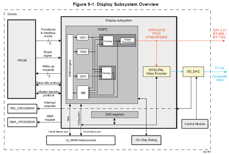
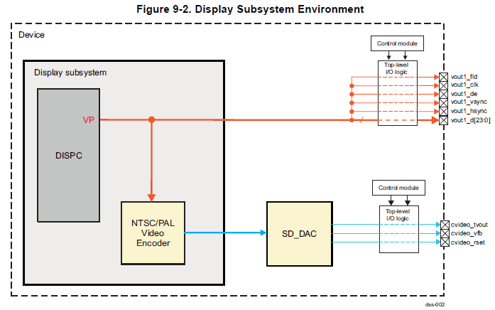
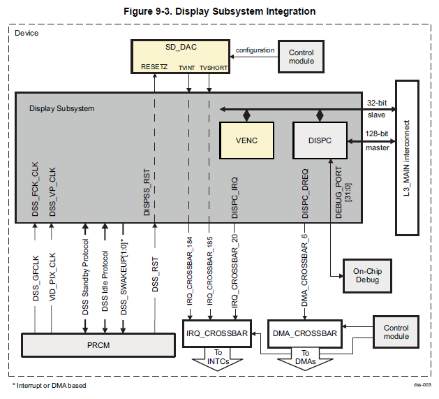
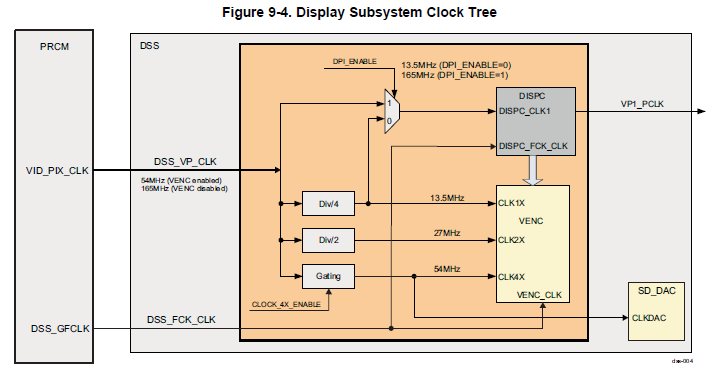
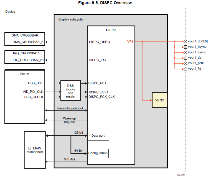
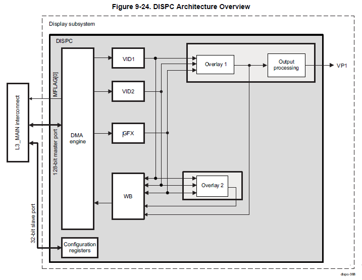
ti dss (display subsystem) (tda3x)

tda3x display subsystem

9.1 Display Subsystem Overview

The Display Subsystem (DSS) provides the logic to interface display peripherals. DSS integrates a DMA engine as part of DISPC module, which allows direct access to the memory frame buffer. Various pixel processing capabilities are supported, such as: color space conversion, filtering, scaling, blending, color keying, etc.

The supported display interfaces are:
• One parallel CMOS output, which can be used for MIPI® DPI 2.0, or BT-656 or BT-1120.
• One TV output, which is connected to the internal Video Encoder module (VENC). The VENC drives a single video digital-to-analog converter (SD_DAC) supporting composite video mode.

The modules integrated in the display subsystem are:

• Display controller (DISPC), with the following main features
– One direct memory access (DMA) engine
– One graphics pipeline (GFX), two video pipelines (VID1 and VID2), and one write-back pipeline
(WB)
– Two overlay managers
– Active Matrix color support for 12/16/18/24-bit (truncated or dithered encoded pixel values)
– One Video Port (VP) with programmable timing generator to support:

• DPI: up to 165 MHz pixel clock video formats defined in CEA-861-E and VESA DMT standards

• VENC: NTSC/PAL standards with 60Hz/50Hz refresh rates
– Supported maximum FrameBuffer width of 4096 for all pixel formats
– Configurable output mode: progressive or interlaced
– Selection between RGB and YUV422 output pixel formats (YUV4:2:2 only available when BT-656
or BT-1120 output mode is enabled)
– Refer to Section 9.2, Display Controller, for more details

• Video Encoder (VENC) with 10-bit standard definition video DAC (SD_DAC). Refer to Section 9.3,
Video Encoder, for more details.
DSS provides two interfaces to L3_MAIN interconnect

• One 128-bit master port (with MFLAG support). The DMA engine in DISPC uses this single master to read/write data from/to device system memory.

• One 32-bit slave port. Used for registers configuration. It is further connected internally to DISPC and
VENC modules.

Figure 9-1 is a high-level diagram of the display subsystem.

9.1.1 Display Subsystem Environment

This section describes the various outputs handled by the display subsystem:
• Parallel interface (MIPI DPI 2.0, or BT-656 or BT-1120) support
• TV (composite video) output support

Figure 9-2 is a diagram of the display subsystem environment.


9.1.2 Display Subsystem Integration
This section describes the integration of the display subsystem module in the device, including information about clocks, resets, and hardware requests.

Figure 9-3 shows the integration of the display subsystem in the device.

9.1.2.2 Display Subsystem Clocks
The power, reset, and clock management (PRCM) module provides the clock signals, and status for their activity, to the display subsystem.

Figure 9-4 shows the details of the display subsystem clock tree.

9.2 Display Controller
9.2.1 DISPC Overview


The DISPC includes the following main features:
• Pipelines for processing:

– One Graphics (GFX) pipeline:
• Pixel formats: ARGB16-4444, ABGR16-4444, RGBA16-4444, RGB16-565, BGR16-565,
ARGB16-1555, ABGR16-1555, ARGB32-8888, ABGR32-8888, BGRA32-8888, RGBA32-8888,
RGB24-888, ARGB32-2101010, ABGR32-2101010, ARGB48-12121212, RGBA48-12121212,
ARGB64-16161616, RGBA64-16161616, BITMAP1, BITMAP2, BITMAP4, BITMAP8. (A
component can be ignored by not selecting Alpha pixel)
• Premultiplied ARGB and RGBA formats
• Selection of the color depth expansion from ARGB16-4444, RGBA16-4444, and ARGB16-1555
to ARGB32-8888, and from xRGB12-4444, RGBx12-4444, and xRGB16-1555 to xRGB32-8888
(replication of the most significant bits [MSBs])
• Support for color look-up table (CLUT): 256 × 24-bit entries palette in RGB
• Support for anti-aliasing on RGB pixel formats using 3-tap filter
• Up to 4K-by-4K frame buffer size

– Two Video pipelines (VID1 and VID2):
• Pixel formats: ARGB16-4444, ABGR16-4444, RGBA16-4444, RGB16-565, BGR16-565,
ARGB16-1555, ABGR16-1555, ARGB32-8888, ABGR32-8888, BGRA32-8888, RGBA32-8888,
RGB24-888, ARGB32-2101010, ABGR32-2101010, ARGB48-12121212, RGBA48-12121212,
ARGB64-16161616, RGBA64-16161616, RGB565-A8, BITMAP1, BITMAP2, BITMAP4,
BITMAP8, YUV422-UYVY, YUV422-YUV2, YUV420-NV12, YUV420-NV21 and in addition
RGBx, xRGB, xBGR, and BGRx pixel formats defined considering that A component of RGBA,
ARGB, ABGR, BGRA pixel formats is ignored by HW (e.g. ARGB->xRGB)
• Premultiplied ARGB and RGBA formats
• Support for color look-up table (CLUT): 256 × 24-bit entries palette in RGB
• Programmable poly-phase filter:
• Independent horizontal and vertical resampling. Upsampling up to x16, and downsampling
down to 1/4
• Maximum input width of 1280 pixels (2560 in 3-tap mode)
• No limitation on the input height
• Supported input formats are all above listed formats, except BITMAP formats. The alpha
blending factor is rescaled like the R, G and B color components. 16 phases with
symmetrical coefficients are implemented.
• Programmable color space conversion from YUV4:2:2 (YUV4:4:4, YUV4:2:0 after Chroma
upsampling through the scaler) into ARGB48-12121212.
• Programmable VC-1 range mapping
• Up to 4K-by-4K frame buffer size

– One Write-back (WB) pipeline: Allows the use of the hardware processing available inside the
DISPC, such as color space conversion, rescaling, and compositing to perform memory-to-memory
transfer with data processing or capturing a displayed frame
• Pixel formats: ARGB16-4444, ABGR16-4444, RGBA16-4444, RGB16-565, BGR16-565,
ARGB16-1555, ABGR16-1555, ARGB32-8888, ABGR32-8888, BGRA32-8888, RGBA32-8888,
RGB24-888, ARGB32-2101010, ABGR32-2101010, ARGB48-12121212, RGBA48-12121212,
ARGB64-16161616, RGBA64-16161616, RGB565-A8, YUV422-UYVY, YUV422-YUV2,
YUV420-NV12, YUV420-NV21 and in addition RGBx, xRGB, xBGR, and BGRx pixel formats
defined considering that A component of RGBA, ARGB, ABGR, BGRA pixel formats is ignored
by HW (e.g. ARGB->xRGB)
• Programmable color space conversion RGB24 into YUV4:2:2-UYVY, YUV4:2:2-YUV2,
YUV4:2:0-NV12, or YUV4:2:0-NV21
• Programmable poly-phase filter:
• Independent horizontal and vertical resampling. Upsampling up to x16, and downsampling
down to 1/4. When the output format of WB pipeline includes a format change from RGB or
YUV4:2:2 to YUV4:2:0, the maximum downscaling provided by the WB scaler is 1/2.
• Maximum input width of 1280 pixels using 32-bit pixels and 5-tap, and 2560 pixels using 32-
bit pixels and 3-tap
• No limitation on the input height
• The supported formats are RGB888/RGBA-8888/ARGB32-8888, ARGB48-12121212,
RGB565-A8, YUV422-UYVY, YUV422-YUV2, YUV420-NV12 and YUV420-NV21
• Alpha blending factor is rescaled like the R, G, and B color components
• 16 phases with symmetrical coefficients are implemented
• Selection of the source of the data:
• One of the overlay manager outputs
• One of the pipeline outputs

• One Video Port (VP1) output:
– Up to 24-bit per pixel on the output interface, with selection between 12, 16, 18 or 24-bit
– Independent programmable timing generator to support up to 165 MHz pixel clock video formats
defined in CEA-861-E and VESA-DMT standards
– Independent programmable multiple cycles output format on 8/9/12/16-bit interface (TDM)
– Configurable output mode: progressive or interlaced mode
– Selection between RGB and YUV422 output pixel format ( YUV4:2:2 only available when BT output
is enabled)

• Two Overlay Managers (OVR1 and OVR2):
– Input Pixel format: ARGB48-12121212
– Output Pixel format: ARGB48-12121212 (A component is only used for Write-back)
– Overlay of the graphics and video pipelines
– Transparency color keys (source and destination)
– Global and pixel alpha blending
– Programmable Z-order (full flexibility)
• Common:
– Programmable 8-bit gamma curve support on VP1 output
– Programmable color phase rotation (CPR)
– Alpha blending support:
• Embedded pixel factor (ARGB and RGBA)
• Global pixel
• Combination of global pixel and pixel factor
• DMA (internal to the DISPC):
– No support for rotation, flip-flop, mirroring and memory fragmentation
– Integrated shared buffers between DMA engine and pipelines
– Programmable buffer thresholds
– Bandwidth limiter on write request (insertion on idle cycles between requests)
• Advanced:
– Mode outputting data on display only from the DMA buffer (self-refresh using the DMA FIFO)
– Arbitration between normal and low priority pipelines (GFX, VID1, VID2 and WB pipelines)
• Power modes:
– Low-power saving modes
– Support on-the-fly dynamic voltage and frequency scaling (DVFS)
– Merge capability of the DMA buffers to support greater OFF period on the L3_MAIN interconnect
• All buffers associated to a single pipeline
• Reallocation of the buffers of the nonactive pipelines to the active pipelines


9.2.4 DISPC Functional Description
The DISPC can read and display the encoded pixel data stored in memory and write the output of one of the overlays or one of the pipelines into system memory.

Several processes can be configured to manage the graphics pipeline (antialiasing) and video pipelines
(VC-1, color space conversion, scaling, and so forth).

The data coming out of a pipeline is sent to the overlay managers (and from there to VP1 or WB), or to
the WB pipeline directly. An overlay manager manages inputs of multiple pipelines. Transparency settings and user timing configurations for VP1 output are available, based on VESA-DMT and CEA-861 standards.

The DISPC allows the capturing of one of the pipeline outputs, or one of the overlay manager outputs, to redirect it into the WB pipeline. It allows the use of the hardware processing available inside the DISPC, such as color space conversion, rescaling, and compositing, and so forth, to perform memory-to-memory transfer with data processing. It can be used as a HW front end compositing unit in order to pre-compose the output frame and write in memory before being fetched again by DISPC for display on VP1.

NOTE: DISPC does not support any tiled frame buffer, nor any compressed frame buffer, and is not
able to generate any compressed output to memory through the write-back pipeline. The DISPC has no capability to support by itself rotation of the frame buffer. 
DISPC can be used for composition using memory to memory transfer. In that case the frame buffer on the input and output can be split into smaller blocks of pixels, processed separately by DISPC. Scaling/filtering of the split blocks requires fetching extra pixels around the processed pixel-block. This can be achieved by properly programming the initial accumulator (accu) value of the polyphase filter inside VID/WB pipelines. The number of taps used by the polyphase filter implies the number of extra pixels to fetch (5-tap requires 2 pixels on left/right/bottom/top to be fetched).

BT-656:
2) Особенности применения протокола цифровой передачи видео данных ITU-R BT.656 при разработке запоминающего устройства записи видеоинформации https://moluch.ru/archive/159/44866/

BT-1120:

7) Implementation of High-Speed 512-Tap FIR Filters for Chromatic Dispersion Compensation http://liu.diva-portal.org/smash/get/diva2:1271001/FULLTEXT01.pdf
9) Implementing FIR Filters in FLEX Devices http://www.ee.ic.ac.uk/pcheung/teaching/ee3_dsd/fir.pdf

Алгоритмы wdrc, dde:

bt.656:

вторник, 22 декабря 2020 г.

Установка 7zip на fedora/ubuntu

1. Ubuntu:

sudo apt install p7zip-full p7zip-rar

Основанные на Debian дистрибутивы идут с тремя связанными с 7zip пакетами:
- p7zip: включает 7zr (минимальный инструмент архивирования 7zip), который может работать только с родным форматом 7z.
- p7zip-full: содержит 7z, который может поддерживать 7z, LZMA2, XZ, ZIP, CAB, GZIP, BZIP2, ARJ, TAR, CPIO, RPM, ISO и DEB.
- p7zip-rar: содержит плагин для извлечения файлов RAR

2. Fedora:

sudo dnf install p7zip p7zip-plugins

Дистрибутивы, основанные на Red Hat, предлагают два связанных с 7zip пакета:
- p7zip: содержит команду 7za, котомая может поддерживать 7z, ZIP, GZIP, CAB, ARJ, BZIP2, TAR, CPIO, RPM и DEB.
- p7zip-plugins: содержит команду 7z и дополнительный плагин для расширения возможностей команды 7za (например, извлечение ISO)

Источники:

понедельник, 14 декабря 2020 г.

Багажник или рейлинги на субару импреза III (2008 г.в.)

Рейлинги от импрезы xv (2012 г.в. - ):
1) РЕЙЛИНГИ ПРОДОЛЬНЫЕ, УСТАНОВКА В ШТАТНЫЕ МЕСТА, СЕРЕБР. ДЛЯ SUBARU XV (5500р.) https://avtobokc.ru/reilingi/reilingi-prodolnye-ustanovka-v-shtatnye-mesta-serebr-dlya-subaru-xv-suxv-73-10-00
2) Установка на Subaru Impreza GH рейлингов от Subaru Impreza XV https://www.drive2.ru/l/501308858740769634

Багажник на рейлинги:
1) Багажник Аэродинамический на рейлинги автомобиля SUBARU Impreza (GD) Универсал 2001-2006г. (Алюминий - Серебристый - Овальный - 120см.) 

Оригинальный поперечный багажник:
1) https://www.drive2.ru/l/509948821111832870/ (12т.р. - проданы)
5) https://www.drive2.ru/l/3057422/ (перечень идентификаторов из оригинального каталога эксзиста)

Дешевый багажник, но который через несколько лет заржавеет (проверено на практике):
1) Багажник универсальный в штатное место Subaru Impreza седан 2007-2011 АЭРО-КРЫЛО - Серый https://www.ozon.ru/product/bagazhnik-universalnyy-v-shtatnoe-mesto-subaru-impreza-sedan-2007-2011-aero-krylo-seryy-192045630/ (3700р.)

суббота, 12 декабря 2020 г.

Ремонт батареи ноута, замена аккумов 18650 (asus, lenovo)

Youtube:
1) Как восстановить аккумулятор ноутбука, пример ремонта - Часть 1 
2) Как восстановить аккумулятор ноутбука, пример ремонта - Часть 2 
3) Аккумулятор ноутбука HP ремонт https://www.youtube.com/watch?v=tBRADOXcIMU&ab_channel=KitayProm
8) Li-ion 18650 где взять, как восстановить, как зарядить https://www.youtube.com/watch?v=AMHJ4XIpo6E&ab_channel=Elektrodroid44RUS

SH79F329AX:
1) Чиним батарею самсунг N150 SH79F329AX https://www.drive2.com/b/573430499331016571/

суббота, 5 декабря 2020 г.

среда, 2 декабря 2020 г.

Магический квадрат

Ссылки:
1) Магический квадрат
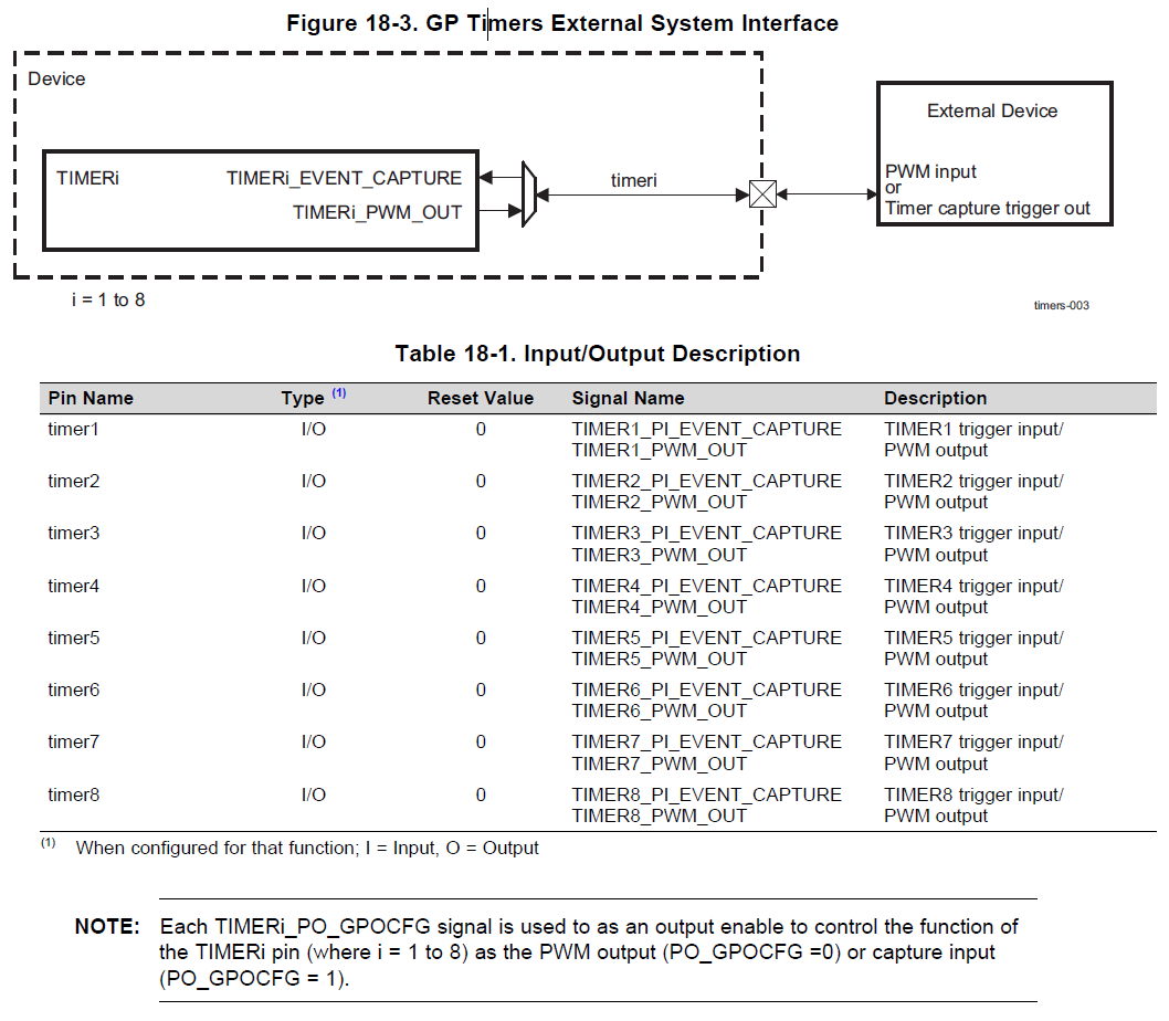
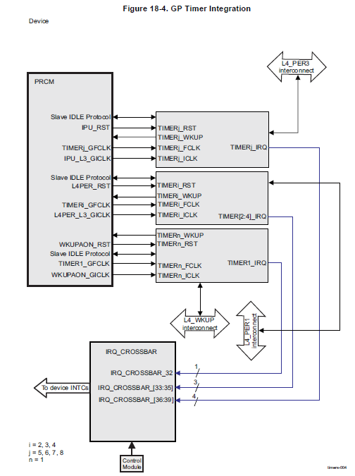
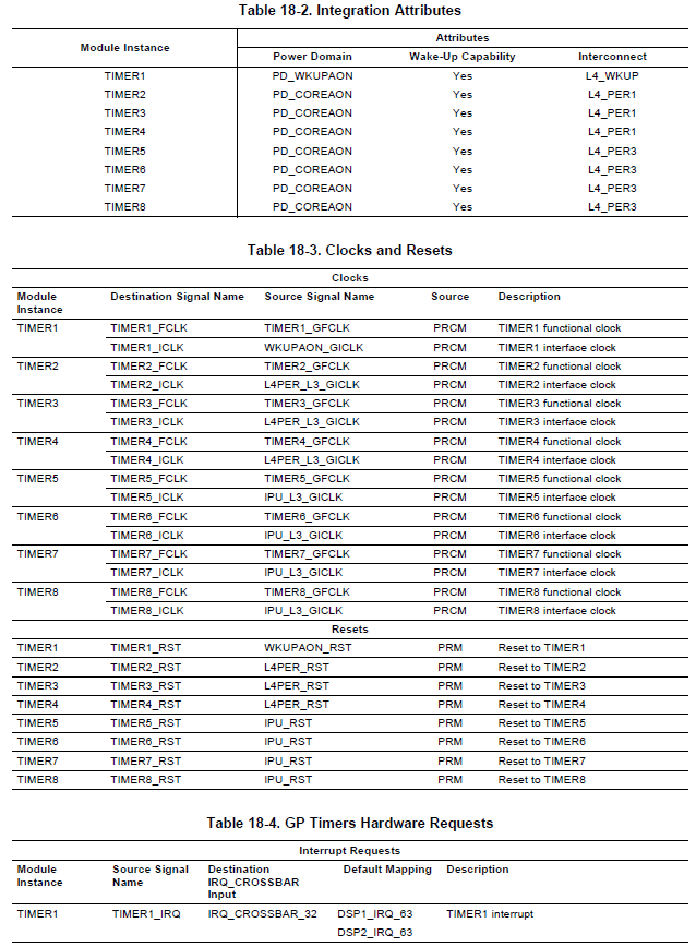
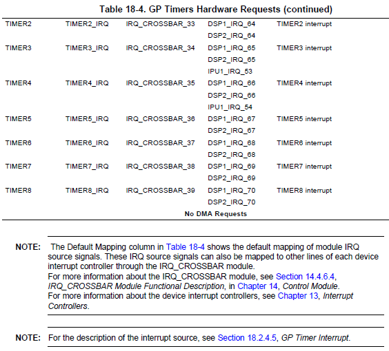
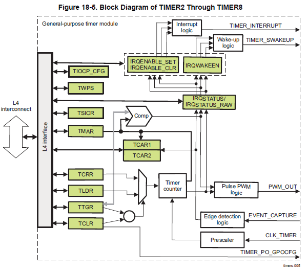
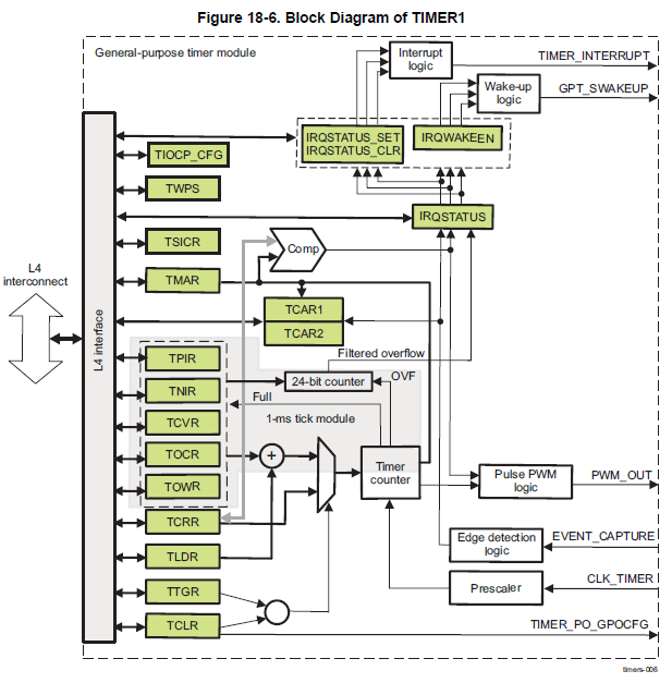
2) Магический квадрат https://habr.com/ru/post/123061/
3) Вычисляем «магические квадраты» с помощью GPU https://habr.com/ru/post/424845/
4) Магическая константа https://habr.com/ru/post/418725/

tda3x timer

18.1 Timers Overview

The device includes several types of timers used by the system software, including eight general-purpose (GP) timers, and a 32-kHz synchronized timer (COUNTER_32K). Figure 18-1 shows a high-level block diagram of the device timers.
The 32-kHz sync timer, which is reset only at power up, provides the operating system (OS) with a stable timing source that stores the relative time since the last power cycle of the product. The eight GP timers, which are useful as basic timers, are included to generate time-stamp-based interrupts to the system software or to use as a source of pulse-width modulation (PWM) signals.

18.2 General-Purpose Timers

18.2.1 General-Purpose Timers Overview

The device has eight GP timers: TIMER1 through TIMER8.
• TIMER1 (1-ms tick) includes a specific function to generate accurate tick interrupts to the operating
system and it belongs to the PD_WKUPAON domain.
• TIMER2 through TIMER8 belong to the PD_COREAON module.
Each timer can be clocked from the system clock (19.2, 20, or 27 MHz) or the 32-kHz clock. Select the
clock source at the power, reset, and clock management (PRCM) module level.
Each timer provides an interrupt through the device IRQ_CROSSBAR.
Each timer is connected to an external pin by their PWM output or their event capture input pin (for
external timer triggering). Figure 18-2 shows an overview of the GP timers.

18.2.1.1 GP Timer Features

The following are the main features of the GP timer controllers:
• Level 4 (L4) slave interface support:
– 32-bit data bus width
– 32- or 16-bit access supported
– 8-bit access not supported
– 10-bit address bus width
– Burst mode not supported
– Write nonposted transaction mode supported
• Interrupts generated on overflow, compare, and capture
• Free-running 32-bit upward counter
• Compare and capture modes
• Autoreload mode
• Start and stop mode
• Programmable divider clock source (2n, where n = [0:8])
• Dedicated input trigger for capture mode and dedicated output trigger/PWM signal
• Dedicated GP output signal for using the TIMERi_GPO_CFG signal
• On-the-fly read/write register (while counting)
• 1-ms tick with 32.768-Hz functional clock generated (only TIMER1)

18.2.2 GP Timer Environment

18.2.2.1 GP Timer External System Interface

Each timer can send or receive stimulus to and from the external (off-chip) system. In the device all timers are configured to output a PWM pulse or receive an external event signal used as a trigger to capture the current timer count. Figure 18-3 shows the external system interface for the GP timers, and Table 18-1 describes the GP timer inputs and outputs.

NOTE: Software control must ensure that MUX mode is configured to select the timeri (where i = 1
to 8) signal on only one pad. Other pads on which the same signal is multiplexed must be
configured in safe mode or non-dmtimer mode to avoid two different pads driving the same
signal. For more information about the configuration of the timeri I/O pads, see Section 14.4.6.1,
Pad Configuration Registers.
18.2.3 GP Timer Integration

Figure 18-4 shows the integration of the GP timer in the device.


Table 18-2 through Table 18-4 summarize the integration of the module in the device.

18.2.4 GP Timer Functional Description

Each GP timer contains a free-running upward counter with autoreload capability on overflow. The timer counter can be read and written on-the-fly (while counting). Each GP timer includes compare logic to allow an interrupt event on a programmable counter matching value. A dedicated output signal can be pulsed or toggled on either an overflow or a match event. This offers time-stamp trigger signaling or PWM signal sources. A dedicated input signal can be used to trigger an automatic timer counter capture or an interrupt event on a programmable input signal transition. A programmable clock divider (prescaler) allows reduction of the timer input clock frequency. All internal timer interrupt sources are merged into one module interrupt line and one wake-up line.

Each internal interrupt source can be independently enabled and disabled by a dedicated bit in the
IRQSTATUS_SET and IRQSTATUS_CLR registers for the interrupt features, and a dedicated bit of the
IRQWAKEEN register for the wake-up of TIMER1. In addition, a mechanism implemented in these timers generate an accurate tick interrupt. For all other internal interrupts, the source can be independently enabled and disabled through the IRQENABLE_SET and IRQENABLE_CLR registers.

For each GP timer implemented in the device, there are two possible clock sources:
• 32-kHz clock
• System clock

The input clock source is selected in the registers in the PRCM configuration (see Section 18.2.1, GP
Timer Overview). 

Each GP timer supports three functional modes:
• Timer mode
• Capture mode
• Compare mode

The capture and compare modes are disabled by default after core reset.

18.2.4.1 GP Timer Block Diagram

Figure 18-5 is a block diagram of the common GP timers, and Figure 18-6 is a block diagram of the GP
timers with a 1-ms tick generation module.


вторник, 24 ноября 2020 г.

Компьютерное зрение (теория)

Обработка изображений:

4) С.Ю. Городецкий - Лекции по методам нелинейной оптимизации http://www.itmm.unn.ru/files/2018/10/Lektsii-po-metodam-nelinejnoj-optimizatsii-GorodetskijSYU.pdf


Фильтр Калмана:
2) Фильтр Калмана — Введение https://habr.com/ru/post/140274/
3) Простыми словами о фильтре частиц https://habr.com/ru/post/276801/
4) Калмановская фильтрация https://basegroup.ru/community/articles/kalmanfilter
5) Particle Filter : A hero in the world of Non-Linearity and Non-Gaussian https://towardsdatascience.com/particle-filter-a-hero-in-the-world-of-non-linearity-and-non-gaussian-6d8947f4a3dc
6) Простая модель адаптивного фильтра Калмана средствами Python https://habr.com/ru/post/328146/
7) Фильтр Калмана — это легко https://habr.com/ru/company/singularis/blog/516798/
8) Фильтр Калмана — !cложно? https://habr.com/ru/post/120133/

Фильтр Лапласа:
2) Краткий курс теории обработки изображений https://hub.exponenta.ru/post/kratkiy-kurs-teorii-obrabotki-izobrazheniy734
3) Учебное пособие по курсу "Компьютерная обработка изображений" (Масочная фильтрация) 

вторник, 27 октября 2020 г.

global/rolling shutter и экспозиция

Global/rolling shutter в матрицах cmos:
1) Global shutter vs Rolling shutter: подробный разбор https://cctvlens.ru/publications/global-shutter-vs-rolling-shutter-podrobnyj-razbor/

Экспозиция в фото:

четверг, 1 октября 2020 г.

bbb, rpi i2c driver on linux

i2c linux driver:
1) Пишем модуль ядра Linux: I2C https://habr.com/ru/post/413249/
4) I2C драйвер в Linux https://blablacode.ru/yadro-linux/583

spi, i2c экраны в посте

i2c example:

windows driver:

Linux start:
1) Что такое Linux? Статья-шпаргалка для новичков 

i2c, uart in ti tda3

1. I2C


2.1. UART integration


2.2. UART functional diagram


ti tda3 (tda3matda3mdtda3mvtda3la):
1) datasheet
2) trm
3) dm505 datasheet

arm cortex-m4:
1) trm
2) generic user guide

вторник, 29 сентября 2020 г.

Популярная электроника

easyelectronics.ru:
1) Методика «канализационной электрики». Основы на пальцах. Часть 1 
2) Резистор, конденсатор, индуктивность. Основы на пальцах. Часть 2
3) Диод, транзистор. Основы на пальцах. Часть 3 
4) Микросхемы. Основы на пальцах. Часть 4 http://easyelectronics.ru/osnovy-na-palcax-chast-4.html

Вики:
1) Z-состояние

среда, 23 сентября 2020 г.

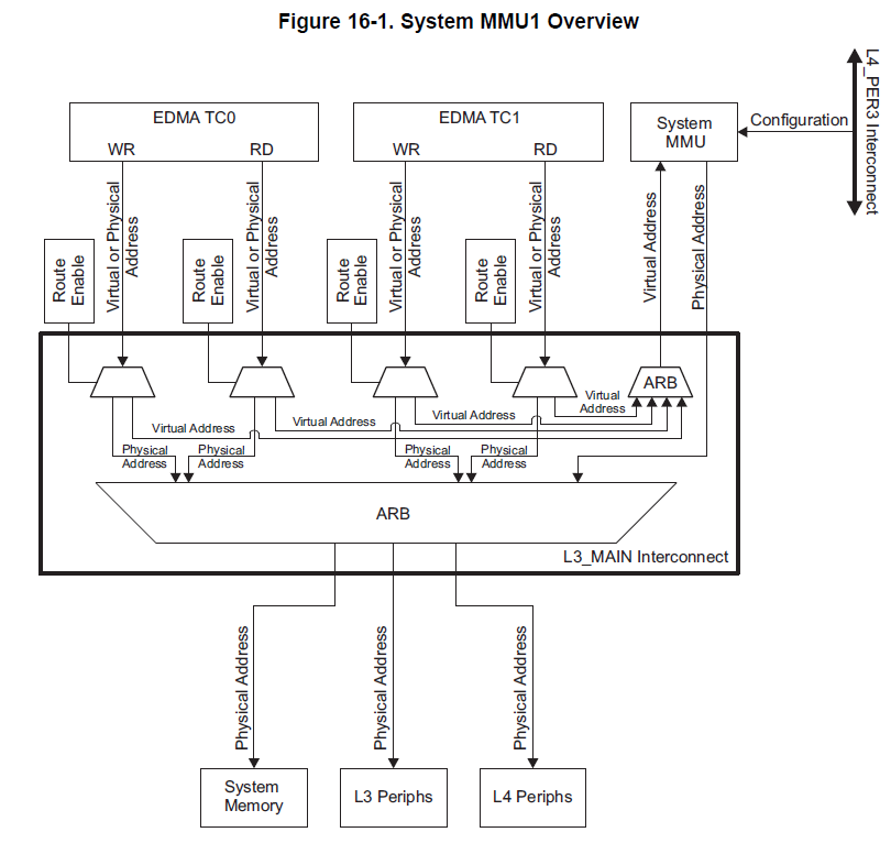
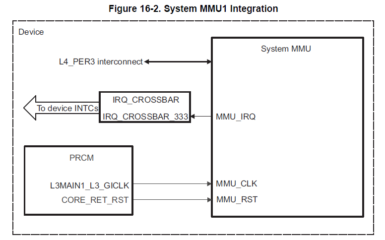
ti memory management units (MMUs)

A memory management unit (MMU) is a hardware component responsible for handling accesses to memory requested by a processing unit, DMA controller, or other bus requestor. MMU functions include:
• Translation of initiator internal (virtual) addresses to physical addresses (that is, virtual memory management)
• Preventing an initiator from making accesses to unmapped pages of the system memory


Two major functional units exist in the MMU to provide address translation automatically based on the table entries:
• The table walker automatically retrieves the correct translation table entry for a requested translation. If two-level translation is used (for the translation of small memory pages), the table walker also automatically reads the required second-level translation table entry. The two-level translation is described later in the chapter.
• The translation look-aside buffer (TLB) stores recently used translation entries, acting like a cache of the translation table.

Translation tables


ti tda3 (tda3matda3mdtda3mvtda3la):
1) datasheet
2) trm
3) dm505 datasheet

arm cortex-m4:
1) trm
2) generic user guide

понедельник, 21 сентября 2020 г.

fpga (cpld) memory mapped register

mmr:
1) Altera + OpenCL: программируем под FPGA без знания VHDL/Verilog https://habr.com/ru/post/269009/
2) Altera + OpenCL: вскрываем ядро https://habr.com/ru/post/269925/
3) Lecture 10: Memory-mapped I/O and Lab 4 David Black-Schaffer http://web.stanford.edu/class/ee183/handouts_spr2003/lecture10_spring2003.pdf

ram, cache:
1) RAM with Simple direct-mapped cache simulation on FPGA in Verilog https://habr.com/ru/post/432320/

dma:
1) SoC: поднимаем простой DMA на FPGA https://habr.com/ru/post/248145/
2) Практическая работа с ПЛИС в комплекте Redd. Осваиваем DMA для шины Avalon-ST и коммутацию между шинами Avalon-MM https://habr.com/ru/post/500016/

arm+fpga:
1) Поднимаем SOC: ARM + FPGA https://habr.com/ru/post/235707/

ещё:
1) Странности синтеза при работе с FPGA https://habr.com/ru/post/413007/

понедельник, 14 сентября 2020 г.

Курсы для детей по scratch, gamemaker

Ссылки:
1) scratch https://kodium.online
2) gamemaker http://kodini.ru/courses/gamemaker#courses-nav
3) minecraft (ComputerCraftEdu) https://foxford.ru/courses/2723/landing

ComputerCraftEdu, scratch:
1) Как установить Minecraft, мод ComputerCraftEdu и Scratch https://academiaguru.ru/kak-ustanovit-minecraft-i-mod-computercraftedu/
2) ComputerCraftEdu [1.8.9] [1.7.10] https://www.geroncraft.ru/computercraftedu/
3) scratch online https://scratch.mit.edu/
4) scratch windows/android download

Аналог scratch (MIT) в РФ:

Python Turtle:
1) Фракталы на Python. Пошаговое руководство https://habr.com/ru/company/piter/blog/496538/
2) turtle — Turtle graphics (перевод на русский - turtle — Черепашья графика)
3) Простое рисование с помощью черепашки https://opentechschool.github.io/python-beginners/ru/simple_drawing.html

habr:
1) Разработка простой игры в Game Maker. Эпизод 0. Первые строки https://habr.com/ru/post/255995/

GameMaker:

Интервью с Марком Овермарсом:
1) GameMaker at 20 – “Sometimes, something small and nameless is way more impressive than one of the big game titles” https://mcvuk.com/business-news/gamemaker-at-20-sometimes-something-small-and-nameless-is-way-more-impressive-than-one-of-the-big-game-titles/

esp32, esp8266 with wifi

esp32:
1) https://ru.m.wikipedia.org/wiki/ESP32
2) ESP32: знакомимся, пишем и запускаем первую прошивку https://m.habr.com/ru/post/309746/
3) Микроконтроллер ESP32 и проекты Arduino https://arduinomaster.ru/platy-arduino/esp32-arduino-raspinovka-arduino-ide/

esp8266 with wifi:
1) IoT-платформа ESP-WROOM-32 DevKit v1 с Wi-Fi / Bluetooth https://amperka.ru/product/esp32-wroom-wifi-devkit-v1
2) Самоходная платформа на МК esp8266 с micropython https://habr.com/ru/post/495576/
3) Очередной Wi-Fi Jammer на Очередной ESP8266 https://habr.com/ru/post/557848/
4) ESP8266: Что внутри «народного wi-fi»? https://habr.com/ru/company/coolrf/blog/238443/
5) 5 экспериментов с WiFi на ESP32 https://habr.com/ru/post/504514/
6) Дружимся с ESP https://habr.com/ru/post/547330/
7) Esp8266 и Lua: первые шаги https://habr.com/ru/post/566756/
8) ESP8266 прошивка, программирование в Arduino IDE https://habr.com/ru/post/371853/
9) ESP8266 с чего начать или первый опыт https://habr.com/ru/post/394535/
10) Схема моего умного дома на основе ESP8266, часть 1 https://habr.com/ru/post/543536/
11) Мой умный дом на ESP8266, часть 2 https://habr.com/ru/post/544328/
12) ESP8266 и Arduino, подключение, распиновка https://habr.com/ru/post/390593/
13) ESP 8266: отправка данных на сайт методом Get запроса https://habr.com/ru/post/543532/
14) Как уменьшить потребление wifi модулей в десять и более раз https://habr.com/ru/post/480316/
15) Разработка умных устройств на примере контроллера теплого пола на ESP8266 https://habr.com/ru/post/412889/

ali:

понедельник, 7 сентября 2020 г.

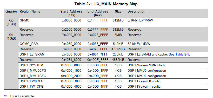
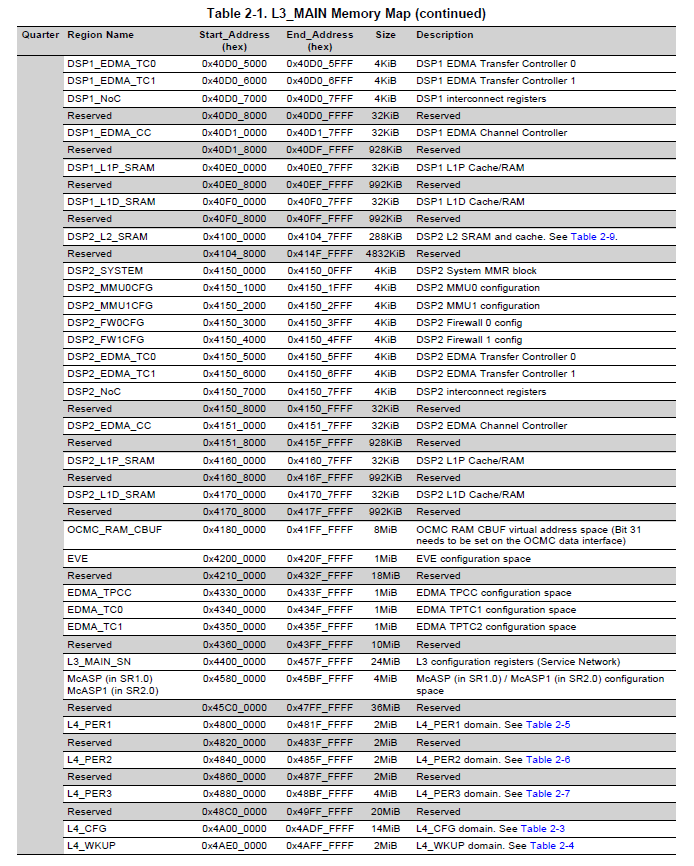
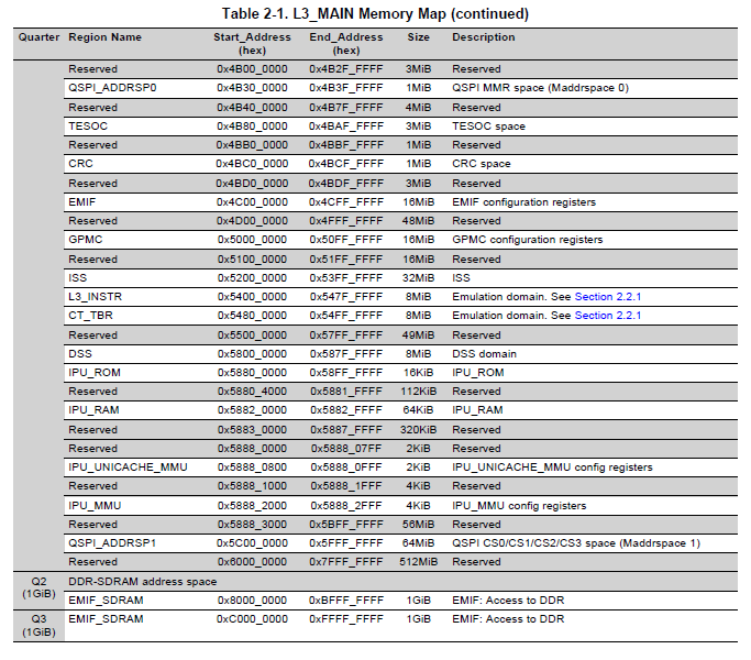
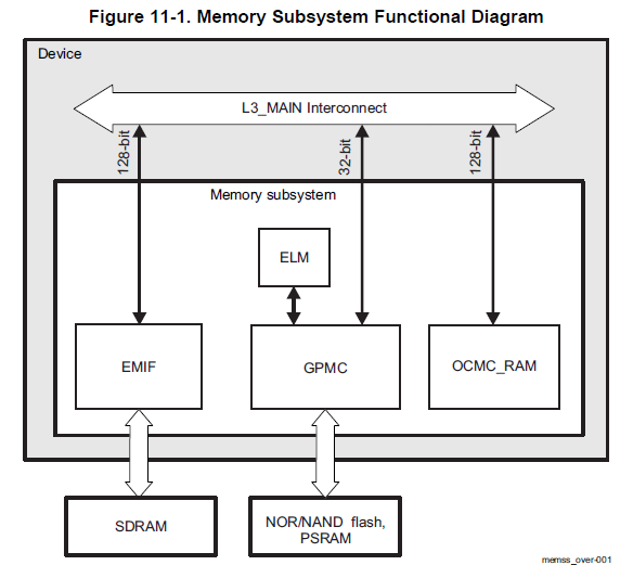
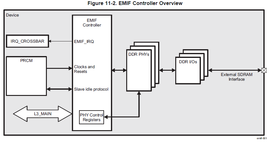
ti tda3 memory mapping (inner nor-, nand-, sram-memories and external sdram ddr), memory subsystem (emif, gpmc, ocm) and interconnect (L3, L4)

 GPMC, EMIF, OCM in L3, L4 interconnect


TDA3 memory map


Memory subsystem
EMIF controller

Ремонт бачка унитаза

 Ссылки:

1) Так делать надо только в том случае, если вы собирались переставлять бак, потому что никак кроме отсоединения бака, закручивания нижней части слива и присоединения бака опять восстановить работоспособность сливной системы не удастся https://youtu.be/Qv7yqWJ-kQU

среда, 2 сентября 2020 г.

Устройство автомобиля (ДВС и электродвигатель)

Вики:
1) Кривошипно-шатунный механизм
2) Двигатель внутреннего сгорания
3) Электрический двигатель
4) Поршень

ДВС -> электродвигатель:
1) https://meduza.io/cards/kak-prevratit-mashinu-v-elektrokar
2) https://www.kolesa.ru/article/elektromobil-svoimi-rukami-kak-zachem-i-skolko-eto-stoit

Оппозитный двигатель и v-образный двигатель:
1) Оппозитный двигатель
2) v-образный двигатель


Стандарты аналогового и цифрового телевидения

Ссылки:
1) https://ru.wikipedia.org/wiki/PAL
2) https://ru.wikipedia.org/wiki/NTSC
3) Автоматическая регулировка усиления
4) Цифровое телевидение
5) Несущий сигнал
6) Видеосигнал
7) Спектр
8) Прогрессивная развертка
9) Чересстрочная развертка

Свет:
1) Дисперсия света

Блины из кислого молока

 Ссылки:

1) https://cookpad.com/ru/recipes/4103275-bliny-iz-prokisshiegho-moloka

четверг, 27 августа 2020 г.

connect old phone lcd to arduino, rpi or stm32

1. phone lcd

1.1. arduino + cell phone lcd (usb):
1) Display for Arduino - Use Smartphone as a Monitor for Arduino https://www.youtube.com/watch?v=LXA4E7MoMxU

1.2. arduino + mobile phone lcd (spi):
1) Подключаем дисплей от сотика или мобильного телефона к Ардуино https://www.youtube.com/watch?v=ShnyOOcfbhc
2) LG KF700 cellphone TFT LCD on Arduino Mega https://www.youtube.com/watch?v=8LEjZMAbedA
3) Arduino TFT LCD Touch Screen GSM Mobile Phone https://www.youtube.com/watch?v=4-6YDET6z9E

1.3. lcd (forums):
1) Reuse old touchscren for Arduino https://forum.arduino.cc/index.php?topic=470884.0
2) using Cellphone/mobile phone display screen https://forum.pine64.org/showthread.php?tid=1923

1.4. arduino lcds:

2. parallel lcd interface, ltdc, dpi:

2.1. RPI DPI:

2.2. arm + ltdc:
1) Праздник жизни по гиковски: с ARM и TFT LCD https://habr.com/ru/post/207136/
2) Нерабочий планшет + Orange Pi https://habr.com/ru/post/396277/

2.3. stm32 + ltdc (hal):
1) STM Урок 58. System Workbench. LCD. SDIO. Часть 1 https://narodstream.ru/stm-urok-58-system-workbench-lcd-sdio-chast-1/
2) STM Урок 64. HAL. LTDC. Часть 1 https://narodstream.ru/stm-urok-64-hal-ltdc-chast-1/
3) STM32: using the LTDC display controller http://www.lucadavidian.com/2017/10/02/stm32-using-
4) Запускаем дисплей на STM32 через LTDC… на регистрах https://habr.com/ru/post/412753/
6) STM32 ОПИСАНИЕ РАБОТЫ LTDC https://hubstub.ru/stm32/171-stm32-opisanie-raboty-ltdc.html
8) Library 18- ILI9341 with LTDC on STM32F429 Discovery http://stm32f4-discovery.net/2014/06/library-18-ili9341-ltdc-stm32f429-discovery/

2.4. stm32 + ssd1963:
1) STM32 и LCD, быстрая заливка экрана https://habr.com/ru/post/278967/
2) 

2.5. stm32 + RA8876, 8080:
1) Подключение дисплея 10" ER-TFT101-1 к STM32F429 через FMC https://habr.com/ru/post/483538/

2.6. stm32 + spi lcd:
1) STM32F1хх — продолжаем лечение от ардуинозависимости при помощи LCD https://habr.com/ru/post/139384/

2.7. stm32 + lvgl library:
1) Интеграция в проект LVGL графической библиотеки для микроконтроллеров https://habr.com/ru/post/510626/
2)